AutoCAD In 3D


For an appreciation of what can be achieved as a result of doing our Autocad 3D
course, see the images and explanations below. Our FREE 3D Autocad course on the
internet could take you to this level of 3D CAD modeling.
(Click the images to enlarge them.)

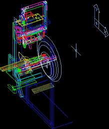
Unlike most published images for 3D modeling tutorials, this one is not a sterile publicity image. It is at a stage of “work in progress” from an actual 3D engineering design that was done on AutoCAD R11 in 1992. (R11 was the current release when this 3D Autocad model was done, and the picture on the left shows how it was in its R11 form back in 1992.) In these pictures, this 3D engineering design is only 80% finished because the images are intended to convey how 3D engineering design takes place in real circumstances.
The design is for a modification to a special purpose machine and how it was arrived at will be explained in a moment. Before that happens, the 3D Autocad models themselves will be explained, because the techniques used in creating them are exactly the same as the ones that can be learned from our Autocad 3D course. Our FREE 3D online tutorial will help you get started.

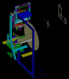
This second image – shown on AutoCAD R14 – is the same view, but has had the R14 Rendering command applied. The rendering helps clarify the outline of the 3D CAD modeling.

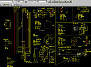
The third view shows some detail drawings derived from the Autocad 3D model used in this special purpose machine design. The projection views are incomplete because computer power was lacking in 1992 and blanking out some of the views helped maintain hardware performance. (The image is again shown on an Autocad R14 screen but if the icons are ignored, it is exactly how it appeared on R11 in1992.)

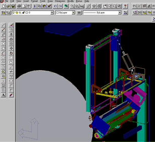
The fourth image is a close up of the top half of the 3D Autocad model, and is shown from a different angle than the first 2 images. It is fairly easy to present Autocad 3D models with less “wireframe” than is shown here, but it is more time consuming, and rarely offers any benefits if the ultimate goal is to achieve detail and assembly drawings. If the model is going to be used for presentation purposes (such as publicity images) it is worth investing a little more time to do better quality models. Our advanced 3D modeling tutorials show how to create mesh surfaces, but you need to work through the simple 3D modeling tutorials on the website to find the correct email address for the advanced 3D modeling. You will also need a full version of Autocad to get the meshed surfaces, because the mesh commands are not available on Autocad LT.
The 3D CAD modeling for this design was minimal because it was a design with the sole objective of creating manufacturing drawings to get parts made. There was no need to do these 3D Autocad models to a 'presentation' standard because it was not used for presentation in any way. The design was successfully implemented within the planned timescales, and within budget. Wiggins Teape were very pleased with the work we did for them, and were amazed that everything fitted first time, avoided collisions with the existing moving parts, and did not need any re-work what so ever.
As for ourselves, it merely re-affirmed what we already knew. Any 3D design method is far superior to 2D methods – and the work was profitable for both us and the client due to a quick turnaround and minimal downtime to modify the machine.
The explanation of what the design was for and how it evolved reveals why the model looks the way it does, rather than looking like the more typical “publicity” type image.
The design brief was to modify 12 special purpose machines. These special purpose machines wrapped large reels of paper up to 1.5mtr diameter, and had to be modified to do a double wrap process instead of a single wrap process. By looking at the top image, the design can be dissected in to 3 main sections. Two of these are easy to see. They are where the entities are most dense. One is at the top of the machine, and the other is at the mid section of the machine. The third portion of the design is made up of everything else. As it happens, the third portion was the start point of the design work, because parts of the existing machine required Autocad 3D modeling. The machine was surveyed and a video taken. This allowed just enough of the machine to be modeled to give the information needed to avoid the existing moving parts and thus design the two sub assembly sections. Over modeling the host wrapping machine would have been a total waste of design effort because it was un-necessary. It is the main reason why the model looks the way it does, and to the untrained eye it would appear to be incomplete. Knowing when to stop adding detail to 3D CAD models ensures efficient use of design resources and is covered in our Autocad 3D course. Once the 3D design of the two new sub-assembly sections was completed, the Autocad 3D models were then used to derive the 2D projections and detail drawings of the parts that needed manufacturing. Finally the assembly drawings were done, and the whole design exercise followed the methods and principles covered by our 3D Autocad course. To get a thorough appreciation of our 3D Autocad course, try our FREE 3D online tutorial.
If you would like to arrange a structured Autocad 3D course with 3D Cadcea, or would like us to undertake some 3D design work, please Email us using our FEEDBACK page in Section E.
To find out our opinion of other 3D systems in use at 3D Cadcea, please Email us using our FEEDBACK page in Section E. We do not sell CAD systems, but are willing to discuss our experiences of a number of software solutions.
| A) ABOUT US | B) UNDERSTANDING 3D | C) INSTRUCTIONS |
| D) GO TUTORIAL | E) FEEDBACK | F) ADVANCED TRAINING |

