SECTION D39 - TASK 39
Projection errors & the vpoint command. Detailing & the drawing environment.


Task Thirty Nine
Rectifying Projection Errors.
Since the views are defined manually using the Vpoint command, human error means that projection errors can easily occur and go un-noticed until the detailing begins. The views set up so far do indeed have a projection error. It is a very easy mistake to make, and a very easy one to put right.
Switch to the drawing environment by picking the layout tab or typing tilemode > 0. If any of the model is obscured, thaw the VPL layer and stretch the Mview windows to reveal the whole model.
The three component models should now be visible in all four windows, as in Fig Tsk 39 with three projection views and one pictorial view. If the Mview borders don't contain what's described, or Mview borders are missing, Thaw and turn on ALL layers.
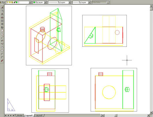
Fig Tsk 39. The start point for a basic assembly drawing
Displaying the whole model this way is the basis for assembly drawings. (Detail drawings need further preparation to isolate the individual parts, and is dealt with soon.)
With the Mview windows visible, study the plan view. It does not align with the view below and this error was a deliberate oversight in task 10 to show just how easy it is to make. Did you spot it prior to seeing the assembly? There is a quick way to correct the plan view. Wrong projection can happen to any view, and the remedy is the same for each case.
Activate the plan Mview by double clicking or typing Mspace and then ensure the Wcs is the active X,Y plane.
The view can now be twisted through 180 degrees using the Dview command as follows:-
| Autocad Command Sequence | Note |
| Command: dview > (For the next step, use a crossing window) | |
| Select objects or <use DVIEWBLOCK>:Specify opposite corner: xx found | |
| Select objects or <use DVIEWBLOCK>:> (Return) | |
| Enter option [CAmera/TArget/..etc../Zoom/TWist/CLip/Hide/Off/Undo]: tw > | |
| Specify view twist angle <0.00 >: 180 > | |
| Enter option [CAmera/TArget/..etc../Zoom/TWist/CLip/Hide/Off/Undo]: > (Return) | |
| Regenerating model. | |
| Command: | |
|
|
|
The Dview command will be used again later for defining auxiliary views.
The views are now all in Third Angle Projection but the plan view will have to be
re-aligned by using a vertical construction line, as was shown in tasks 15 and 16.
(Re-read task 15 and 16 if needed.)
Begin re-aligning the views by de-activating the plan Mview. (Double clicking outside the Mviews OR type Pspace.)
Start the vertical construction line (with F8 ortho switched on) from the centre of the circle in the bottom right-hand view. Finish the construction line where the plan view is supposed to be. Finally, read the "useful tip" below and then pick and move the Mview plan as described in the tip. Erase the construction line when the view is positioned.
USEFUL TIP
When aligning the plan Viewport to the correct position, use
"Cen" to pick the centre of the circle on the yellow layer when prompted for the Base Point.
Position the plan Mview at the end of the vertical construction line. Despite the yellow
circle looking like a line in the plan view the centre can still be picked. To an onlooker
it will appear that the mid point of a line has been picked. It's useful to remember that
the entity is always a circle, regardless of the projection being viewed, and thus will obey
commands as a circle even when the projection gives the impression that the circle is a line.
Please feel welcome to make use of the free resources at the side and bottom of these webpages. Many of them contain very useful 3D CAD material.


