SECTION D44 - TASK 44
Auxiliary views with Autocad. Component layers and UCS.


Task Fourty Four.
There are situations that often require an auxiliary view. The component on layer 03 is a good example as shown in fig Tsk 44. Since it's triangular and has a face with a drilling it needs an auxiliary view. Some of the preliminary work for defining an auxiliary view has already been done in task 35 by pre-defining a Ucs. The Ucs was defined to position the hole in the angled face, and was named as 7. Here's how to set up the Auxiliary projection.
Zoom in to the four views of the triangular item. Copy the existing pictorial Mview to a convenient location. Activate the new view.
The following steps force the view to be square to the named Ucs, and since Ucs 7 is on the angled face, (task 35 created the named UCS), then the face will also be projected squarely.
| Autocad Command Sequence | Note |
| Command: ucsfollow > (This is a 'setvar' variable) | |
| Enter new value for UCSFOLLOW <0> 1 > | |
| Command: ucs > | |
| Current ucs name: *WORLD* | |
| Enter an option [New/Move..etc../Restore/Save/..etc..]: r > | |
| Enter name of UCS to restore or [?]: 7 > (The view is now square to the screen) |
|
| Regenerating model. | |
| Command: ucsfollow > | |
| Enter new value for UCSFOLLOW <0> 0 > | See a./ |
| Command: | |
| a./ This is an important step to reset UCSFOLLOW to zero, but only after the view has been set squarely to the screen. If it is not done, the view will not remain in place. It will change to reflect ALL future Ucs changes. |
|
Reset the Wcs to be current using UCS, W. The view should have remained square to the screen when setting ucs - w. If it doesn't, ensure the instructions in the panel above were followed carefully. Deactivate the Mview.
Although the new view is projected square, it isn't rotated to suit the angled face of the triangular plan view. The Dview command from task 39 needs to be used again, but before it can be used, the desired TWist angle has to be established. This will be done by using the " Distance" command on the angled line in the plan view of the wedge. (Autocad will return some values in a moment, and some versions use the command window to display them. Ensure the command window is large enough to read these values.)
| Autocad Command Sequence | Note |
| Command: dist > | |
| Specify first point: end > of: (Pick the bottom left of the angled line) |
|
| Specify second point: end > of: (Pick the upper right of the angled line) |
|
| Distance = 45.0694 (1.8028ins),Angle in XY Plane = 56.3099, Angle from XY Plane = 0.000, Delta X = 25.0000 (1 inch), Delta Y = 37.5000 (1.5 ins), Delta Z = 0.0000 | |
| Command: | |
Depending on the software version used, AutoCAD displays a number of values (5 or 6) on completion of this command. The important one in this instance is the " Angle in XY Plane = ..." Note the value down.
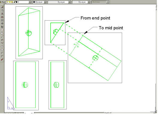
Fig Tsk 44. Creating an Auxiliary view.
It is important to understand the direction of the angle measurement and thus understand
the degree of twist needed to set up the auxiliary view. Assuming that AutoCAD is set with
traditional degrees measured from mathematical zero, (i.e. measuring anti-clockwise
from the horizontal - as set up in task 2), take time to understand the
angle value that AutoCAD returns after using the Dist command.
Using the noted value, try and deduce the amount of twist that will be needed when
the Dview command is invoked.
Switch to Mspace and ensure the world Wcs is set. Highlight as active the view
you made square. Apply " Dview-twist" to this view as follows:-
| Autocad Command Sequence | Note |
| Command: dview > (Pick the cmpt03 block with a crossing window) |
|
| Select objects or <use DVIEWBLOCK>: Specify opposite corner: 1 found | |
| Select objects or <use DVIEWBLOCK>: > (Return) | |
| Enter option [CAmera/TArget/..etc../Zoom/TWist/CLip/..etc..]: tw > | |
| Specify view twist angle <0.00>: 56.3099 > | See a./ |
| Enter option [CAmera/TArget/..etc../Zoom/TWist/CLip/..etc..]: > (Return) (The view is now square to the screen) |
|
| Regenerating model. | |
| Command: | |
| a./ A value will need to be established every time an auxiliary view is defined - read the next instruction. |
|
Experiment with the twist angle value if need be. Once the view has the amount of twist required for a correct Auxiliary projection, deactivate the mview.
If future models have angled faces in different planes, it will be necessary to make each face square to the screen by constructing a Ucs in the plane of the required face, saving its Ucs and then using Ucsfollow. When a face is square to the screen the Dview-twist command can be used to set the auxiliary angle.
Stretch the auxiliary view to see the whole component. (Don't worry at this stage if view scales seem to be different - it will be corrected soon.) Move the Auxiliary view close to the plan view to verify the relevant edges are parallel. If the relevant lines aren't parallel, repeat the Dview - twist process. Deactivate the mview when the Auxiliary projection is correct.
If scales appear to be different, "List " each Mview by picking the border to see the XP value given. (Even if they seem correct, "List" each view anyway.) If for any reason the XP values differ, reset them by activating the Mview and zooming to 0.5XP as shown in task 14. Deactivate the Mviews and move them to make room for the new auxiliary view. Ensure the 3 projection views remain aligned and stretch the auxiliary view so it is fully visible in its mview.
If "List " is used on an Mview border without it being highlighted, data regarding the Viewport, such as Viewscale and layer, is displayed. If "List" is used on the line entities when the Mview IS highlighted, data regarding the modelled entity is returned.
When the auxiliary view is at the correct angle and correct zoom xp, the view has to be accurately positioned. Referring to Fig TSK 44 will be helpful while positioning the auxiliary projection. Start by moving it such that the parallel lines of the two views are on top of each other. See the broken lines in fig TSK 44. Now move the auxiliary view away from the plan view by picking a line end in the auxiliary view and moving it to its own mid point, shown solid in fig TSK 44, thus maintaining the projection. When positioned, dimensioning could begin - and does so with task 46. However, one stage still needs completing.
Fig Tsk 44. Creating an Auxiliary view.
Please feel welcome to make use of the free resources at the side and bottom of these webpages. Many of them contain very useful 3D CAD material.


