SECTION D41 - TASK 41
Layer management & 3D design assemblies. sub-assemblies, Wblock & Xref.


Task Fourty One.
Isolating Assembly Components.
Layer management is an important part of working in 3D because it is used to show components individually while still assembled. Parts can also be shown individually by using Wblock and/or Xrefs but this is poor because design quality relies heavily on having accurate assemblies. Furthermore, accurate assemblies allow BOMs / schedules to be created easily using the list command. (This is discussed later.) With wblocks / Xrefs, it is easy to lose track of the most up-to-date parts because other users can make changes not realising the part is used in other assemblies. The layering shown here doesnt have to be applied rigidly - it shows a versatile layering scheme that works very well for most cases. Work through the tasks to understand the layer issues for 3D design and develop the technique at a later date to your own needs for isolating components.
Layers are used to display components separately even though the assembled model hasn't been split up. The quality of the design work DEPENDS on an accurate ASSEMBLED model so splitting into its individual component parts is to be avoided. (Entire assemblies can be separated in to smaller sub-assemblies, and a method for it is covered Section G of this website.)
Layer management can become complicated so this task serves as a simple example of the layering principles. A deeper insight is given in the next task.
At present there are three components on separate layers. The principle is to freeze two of the three layers in a specific view (or views) thus leaving the component on the unfrozen layer still visible. See fig Tsk 41.
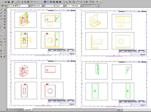
Fig Tsk 41. Freezing layers to show only the individual components.
The command to freeze layers in a Viewport is slightly different to the usual "Layer" command.
Ensure no Mviews are active and zoom in so all 16 Mviews fill the display area.
Proceed as follows:-
| Autocad Command Sequence | Note |
| Command: vplayer > | |
| Enter an option [?/Freeze/Thaw/Reset/Newfrz/Vpvisdflt]: f > | |
| Enter layer name(s) to freeze or <select objects>: 02,03 > | See a./ |
| Enter an option [All/Select/Current] <Current>: s > | See b./ |
| Select objects: Specify opposite corner: 4 found (Using a crossing window.) | |
| Select objects: >(Return) | |
| Enter an option [?/Freeze/Thaw/Reset/Newfrz/Vpvisdflt]: >(Return) | |
| Command: | |
| a./ Layer 1 is missing because it is going to remain visible. b./ Select the 4 viewports within the bottom left drawing sheet. |
|
The four views chosen now display only the red layer 01 component.Repeat the above steps for the top right and bottom right sets of A3 / B size bordered Viewports, but freeze layers 01 and 03 in the top right drawing, (to leave the layer 02 component displayed), then 01 and 02 in the bottom right drawing, (to leave the layer 03 component displayed). The top left set of bordered Viewports will not have anything frozen because these views are going to remain as an assembly drawing. The A0 sheet should now resemble fig Tsk 41 with three individual components as detail drawings, and one assembly drawing. Although unnecessary at the moment, to re-reveal the components just frozen, the Vplayer - thaw option would be used.
The above steps can be done by using the layer window when in the drawing environment. It has extra columns on the right hand side for vplayer that apply to an active Mview. Experiment with it after completing the training.
Look carefully at the projections of the layer 2 component in yellow. Notice the protruding shaft has a solid line running through it where a centreline would normally appear. This is the disadvantage of wire type cylinders that was mentioned in task 38. These solid lines running through shafts are the unwanted entities and occur in elevations and plan views. It is possible to simply erase them from the model. To do so would leave the shaft as two flat end disks. The unwanted entities (unwanted in detail drawing projections) are the quadrant lines that join the disks. This situation is a nuisance but there are several work around solutions shown in Appendix I under "unwanted entities." Work through the appendices at the end.
The steps above have shown components as separate items without splitting them from the assembly. Retaining
an assembly model is vital if you want to ensure...:-
1./
High quality designs that avoid unwanted interferences and component clashes,
2./
Getting accurate parts lists data showing what components make up the assembly.
Task 41 demonstrates the principle for showing components separately very well. In the real world, a design model is likely to have far more than three components and thus layer management becomes an important point if 3D methods are to be used effectively. The next section describes a layer structure to display components separately for models with several assemblies and hundreds of components. The principle is similar to task 41, but instead of freezing layers that contain entities, layers that contain blocks will be frozen. Each block represents an individual component. A suitable naming convention for blocks and layers is also introduced.
LAYER MANAGEMENT FOR COMPLEX DESIGNS.
THE PRINCIPLES OF MODELLING ARE EXACTLY THE SAME FOR COMPLEX ASSEMBLIES AS THEY ARE FOR THIS SIMPLE ASSEMBLY. The same is true for displaying the components separately, except the layering principles need to be developed further.
Until now the layering has been straightforward - one layer per component. For complex models, this would be very inefficient. If each layer had model entities the result would be an un-manageable layer structure when it came to detailing, and a slow computer because of the large number of inefficient single entities. The best way to proceed is to make each component into a block after it has evolved into a firm design.
In cases where there are many hundreds of components, it's useful to adhere to a layer structure arranged into 3 groups.
Group 1.
Layers for modelling. Entity layers.
Group 2.
Layers for component blocks. One block to represent one component. Each component resides on a
different layer and has a unique block name.
Group 3.
Layers for assembly blocks. Groups of component blocks arranged into a larger block to represent
an assembly.
Group 1 - Layers for individual entities.
The first group comprises a limited number of coloured layers. These are usually layer 01 to
layer 16 and solely for model entities / component creation. These numbered layers are used for
entity data only.
(The model so far has used the first three layers. If you intend to adopt 3D design methods you will
need to create all the layers described in this section up to task 42. Feel free to create
them while working through this section, or alternatively, if you want the minimum number of
layers to complete this tuition, continue to read this section and you will be prompted to create
the minimum number of "tuition" layers in task 42.)
No blocks will be created on these entity layers. Every un-blocked component, dimension line,
text, or any other individual entity should reside on one of these entity layers. Layer changes
ONLY OCCUR WHEN ENTITIES BECOME A BLOCK.
The number of entity layers will depend on the colour capacity of the computer being used, and using different colours aids component recognition. If colour capacity is limited then the first ten layer names and colours would be as follows:-
Layer 01 = colour 1 (Red)
Layer 02 = colour 2 (Yellow)
Layer 03 = colour 3 (Green)
Layer 04 = colour 4 (cyan)
Layer 05 = colour 5 (Blue)
Layer 06 = colour 6 (Magenta)
Layer 07 = colour 7 (White)
Layer 08 = Light grey
Layer 09 = Mid grey
Layer 10 = Dark grey
(Layers 08, 09 and 10 are intended for detailing.)
Some experimentation is needed to set colours to layers 08, 09 and 10. Experiment until you
have satisfactory shades of grey. These grey layers will be used for dimensions, text, center
lines etc.
If the colour capacity is still available, 6 more layers can be set to darker shades of layers 01-06.
Layer 11 = colour Dark Red
Layer 12 = colour Dark Yellow
Layer 13 = colour Dark Green
Layer 14 = colour Dark Cyan
Layer 15 = colour Dark Blue
Layer 16 = colour Dark Magenta
There are advantages to modelling and drawing with this colour / layer relationship. The reasons are as follows:-
A. Recognition.
The basic working layers can be identified on sight by their colour. The method hinges on knowing
the first six AutoCAD default colour numbers. At worst these are easily learned, at best regular
users will undoubtedly already know them.
1 = RED
2 = YELLOW
3 = GREEN
4 = CYAN
5 = BLUE
6 = MAGENTA
Once the colour is known, the layer can be recognised since colour 1 (red) is used on layer 01
and dark red is on layer 01+10, i.e. layer 11. Because of this colour / layer relationship,
layers are identified from colour recognition without having to perform a time consuming "list" to
identify a layer. The differing colours aid component recognition as a design becomes congested.
B. Convenience.
The layers 08, 09, and 10 are used for detailing and can be assigned with lesser thicknesses
for plotting. This is done by assigning a finer pen or finer line weight to these three layers.
All other layers remain as heavy outlines for modelling. Predictable line thicknesses for plotting
are easily achieved.
For older software, layer manipulation using wildcard characters is easier - such as 1* or 0* - and
is useful for de-congesting a model.
C. Customisation.
Customisation benefits because the area set aside for layers containing active entities (layers 01-16)
remains fixed at 16 locations for all designs, large, or small.
Group 2 - Layers for complete items after becoming a block.
The second group of layers are for the individual components after they have been made into blocks. The idea is to block the components after they are fully designed. The block name (or number) and layer name (or number) should be exactly the same. E.G. Suppose a detail drawing is going to be numbered as "LG-430/c." The component in that drawing should be on a layer called "LG-430/c" and exist as a block, the block also being called "LG-430/c." As the number of layers / blocks in this group increase, their layers can be frozen, again using wildcard characters, leaving the base modelling layers 01-16 active.
There are good reasons for freezing layers with blocks on them.
1./ - Blocks are efficient and help keep the software speed high.
2./ - Freezing layers reduces the software workload even more.
3./ - Freezing layers is an excellent way of de-congesting the model during the design phase.
Regarding the last point, when individual "blocked" parts require work at a later stage, they can be individually thawed and worked on in isolation, with ALL the other block layers frozen. This is demonstrated later in Task 47 showing the principle in full with an up-issuing example.
Group 3 - Layers for complete assemblies after becoming a block.
The third group of layers are for the assemblies. These are made from groups of the pre-blocked components that result from group 2 above. The layer numbers should also be the same as the assembly drawing numbers. E.G. Suppose an assembly drawing is to be numbered as "01-ASSY-RIG." The assembly should be on a layer called "01-ASSY-RIG" and exist as a block, the block also being called "01-ASSY-RIG."
Note
With the groups 2 and 3 above, if part and assembly numbers are NOT available when a design is at
the concepts stage, use layer names like CMPT01, CMPT02...CMPT# for components and ASSY01, ASSY02...ASSY#
for assemblies. For issue levels use names like "Rev1" or "ISSA". Colors are not
required for layers with blocks - I.e. the CMPT, ASSY, or ISS layers.
Below shows a full compliment of layers for each of the 3 groups.
Group 1 layers as follows:-
01 = Red
02 = Yellow
03 = Green
04 = Cyan
05 = Blue
06 = Magenta
07 = White
08 = Light grey (For Dimensions.)
09 = Mid grey (For Dimensions.)
10 = Dark grey (For Dimensions.)
11 = Dark red
12 = Dark yellow or orange
13 = Dark green
14 = Dark cyan
15 = Dark blue
16 = Dark magenta
CL = Centerline
HL = Hidden line
PL = Phantomline
VPL = Viewport layer
Group 2 layers as follows:-
CMPT01, CMPT02, CMPT03, ... CMPT..#
Group 3 layers as follows:-
ASSY01, ASSY02, ASSY03, ... ASSY..#
Issue level (Revision) layers as follows:-
ISS01, ISS02, ISS03, ... ISS.#
Only one set of CL, HL, PL lines are needed because ALL plots are done at 1:1 regarding the paper size. (This was demonstrated in Task 14.) Once the line scales (LTscale) are set correctly to be suitable for all the drawing sheets, they won't need to be changed with drawing scale, because they appear only in paperspace not modelspace.
Applying 3D methods to different design disciplines.
The layering methods described above mimic a part number structure using "CMPT" and "ASSY" layer names instead of genuine drawing and part numbers.
If the 3D Model uses components and assemblies with genuine part numbers and drawing numbers, the block and layer names need to be set to use the same part numbers and drawing numbers. By doing this, the CAD model will generate the bills of material automatically. This is because items are often called by their part number on a bill of material and by using the "List" command on an assembly with layers and blocks that are the same as the part / drawing numbers, the resulting printout will look like a bill of materials.
The 3D deisgn methods in these tutorials will apply equally to all the design professions - Mechanical, Architectural, Building services, Interior design and Process plant. This might sound like a sweeping statement but the technical differences between these professions lie in the symbols and nomenclature appearing on the drawings, not the design shapes and projections. The method of shape creation on a CAD model is consistent regardless of the design discipline. For example, take a small part of some CAD model like a corner piece, 50mm thick, with a radius of 75mm. Irrespective of the industry, the shape will be modelled the same way - as just the shape. No dimensions, no representative symbols, and no material data. Mechanically it might be a piece of mild steel with a specific strength grade, a high tolerance, and specific type of finish. Architecturally it might be made of a particular type of stone. The differences arise from secondary information attached to the drawing, not from the way the shape is modelled in 3D.
Each industry will use the same approach to create 3D CAD geometry. Although different industries will have different 3D shapes modelled, it is the layer / block names and information put on the drawings that differentiate the disciplines.
The layer names example cited above, using "CMPT" and "ASSY" layers, is a general case that works well for most designs before the part numbers and drawing numbers are known.
Please feel welcome to make use of the free resources at the side and bottom of these webpages. Many of them contain very useful 3D CAD material.


