SECTION D43 - TASK 43
Creating auxiliary views. Component block & assembly block. Zoom scale factor.


Task Fourty Three.
This task will use component block and assembly block layers.
Pay close attention to the instructions in this task. Do not mis read the instructions by
trying to go quickly.
Zoom to the red box to show just the four views. Activate the pictorial view, and use
Ucs > w to set the world ucs (wcs.) Make "CMPT01" the current layer.
(The layer on which the block resides will be the same as the current layer when objects are
selected, in this case layer "CMPT01.")
Type the command Block. . .
Newer software will give a window. Older software gives prompts in the text area.
The instructions for older software are in the next paragraph, while for newer software they are after Fig Tsk 43. (Fig Tsk 43 applies to newer software only.)
To create the block in older software the sequence is block > cmpt01 > 0,0 > c pick the entities followed by return. The box vanishes and needs to be reinserted using insert > cmpt01 > 0,0 followed by 3 returns to accept the scale factors and rotation values. The next paragraph after Fig Tsk 43 explains the steps for newer software. If you are using older software, ignor the next paragraphs and then continue to follow the instructions.
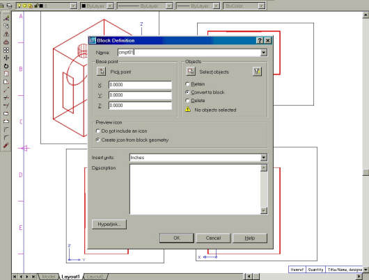
Fig Tsk 43. Creating blocks with newer software.
After typing block the window shown in Fig Tsk 43 appears.
Create the block as follows:-
In the name field at the top of the window, type cmpt01.
Just below the name field are two sub windows called Base point and Objects.
Ensure that X, Y, and Z are set to zero in the Base Point box. In the Objects
window ensure the Convert to Block option is selected. Finally, choose the Select Objects
icon in the Objects window.
The Block Definition window vanishes momentarily.
Use a crossing window to pick all the entities of the red box in the pictorial
view. After picking, press return and the Block Definition window re-appears. Click the
OK box at the bottom.
Now do the same steps WITH CARE for the yellow and green components as follows:-
Deactivate the Mview and then Zoom to the four views of the yellow component
and activate the pictorial view.
Using the same steps as were used for the red component, set layer CMPT02 to
be current, activate the Mview, and create a block of the yellow item. Call the
block "CMPT02" while in the Wcs. It is VITAL to have layer CMPT02 current before creating
the block.
Do the same for the green component calling it "CMPT03" with "CMPT03" as the current layer. On completion, deactivate the Mviews and do a Zoom All. The display should still look as it did in FigTsk 41.
Task 41 has already demonstrated how components can be individualised, when on separate layers, by freezing the unwanted layers in a specific view. Task 41 was a simplified example by freezing the entity layers. For "live" design situations with blocks, the principles are exactly the same. Instead of freezing unwanted "entity" layers in a view, the unwanted "CMPT" block layers (the ones just created) are frozen. In a "live" design the chain of events is:-
1. Create components on the entity layers 01 to 16.
2. Set the components to "CMPT" blocks on "CMPT" layers.
3. When at the drawing stage, freeze and thaw only the "CMPT" layers. Entity
layers remain unfrozen. (Entity layers would be temporarily frozen from time to time
during the modelling phase.)
To demonstrate freezing the "CMPT" layers, the entire model needs to be seen as it was in fig Tsk 40 on page 68. To achieve these conditions, thaw all the Vplayers using the wildcard character * as follows:-
| Autocad Command Sequence | Note |
| Command: vplayer > | |
| Enter an option [?/Freeze/Thaw/Reset/Newfrz/Vpvisdflt]: t > | |
| Enter layer name(s) to freeze or <select objects>: * > | |
| Enter an option [All/Select/Current] <Current>: a > | |
| Enter an option [?/Freeze/Thaw/Reset/Newfrz/Vpvisdflt]: > (Return) | |
| Regenerating layout. | |
| Regenerating model. | |
| Command: | |
|
|
|
The entire assembly is again visible in each window as it was in fig Tsk 40. The " CMPT" blocks can now be shown as individual items.
Apply the " Vplayer" command again, (used in task 41), but this time freeze out ONLY the relevant CMPT layers as described below, NOT the individual coloured layers. For the red box component in the lower left window, proceed as follows:-
| Autocad Command Sequence | Note |
| Command: vplayer > | |
| Enter an option [?/Freeze/Thaw/Reset/Newfrz/Vpvisdflt]: f > | |
| Enter layer name(s) to freeze or <select objects>: cmpt02,cmpt03 > | a./ |
| Enter an option [All/Select/Current] <Current>: s > | b./ |
| Select objects: Specify opposite corner: 4 found (Using a crossing window) | |
| Select objects: > (Return) | |
| Enter an option [?/Freeze/Thaw/Reset/Newfrz/Vpvisdflt]: > (Return) | |
| Command: | |
| a) Layer cmpt01 is missing because it is going to remain visible. b) Select the 4 viewports within the bottom left drawing sheet. |
|
The four views chosen now display only the red component. - if not, read the last paragraph below, which also applies if you get display errors later in the task.
Show the yellow component in the top right Mviews by using Vplayer to
freeze layers CMPT01 and CMPT03.
Show the green component in the lower right Mviews by using Vplayer to freeze
CMPT01 and CMPT02. When the screen appears as it did in Fig Tsk 41, save your
work.
The top left set of bordered Viewports will not have anything frozen because these views are going to remain as an assembly drawing. Using the " CMPT" layers in this way is the key to handling hundreds of components. It allows large design projects to be managed effectively for model splitting into main assemblies, and for up-issuing as will be shown in task 47. All individual entities remain on entity layers but components can still be frozen independently by using the CMPT## layer names. The principle is also used for assembly blocks, and will be done soon.
Problems can occur easily with mistyped block names and not having the correct current layer set when creating the blocks. If you are not able to achieve what is described then use undo to the last save in task 42 and re-do the work in task 43 more carefully than last time.
Creating An Auxiliary View.
During the next two tasks you will need to activate and deactivate Mviews frequently, and from the tasks so far, you should have an understanding of how this affects Viewports while in the drawing environment. (Review tasks 10 and 11 if need be.)
Please feel welcome to make use of the free resources at the side and bottom of these webpages. Many of them contain very useful 3D CAD material.


