SECTION D21 - TASK 21
Layers, UCS command, views, entities & the XY plane.


Task Twenty One
The first new component is going to be an unequal 90 degree angle section with its end edge flush to the box face with the rectangle. It will also be in contact with the base of the box and the face opposite the one with the circle. Since layer 02 is current the new entities will be on layer 02 and should also appear as colour 2 (yellow).
If not already in use, restore view 7. (For newer software, see the bottom paragraph of task 5. For older software see the third paragraph after the note of task 5.) Use the UCS command to rotate the XY plane by minus 90 using the Y option so it is parallel to the box face with the rectangle on it. (To re-cap UCS, see the first command panel of Task 8.)
Draw around two edges of the face shown yellow in fig TSK 21.
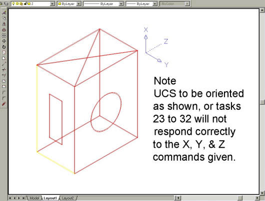
Fig Tsk 21. UCS Orientation.
Note
If the Ucs isn't oriented as shown in fig TSK 21, tasks 23 to 32 will not respond correctly
for the values and X, Y, Z directions given in the training. Ensure the Ucs is set to the
same orientation shown in fig TSK 21. Note the X and Y letters on the arrowheads.
Please feel welcome to make use of the free resources at the side and bottom of these webpages. Many of them contain very useful 3D CAD material.


