SECTION D36 - TASK 36
UCS orientation and entity thickness.


Task Thirty Six
Adding the third component.
Set layer 3 to be current. The UCS should currently be oriented the same way as shown on the previous page in Fig Tsk 35. If it isnt in the same orientation as Fig Tsk 35, then restore it by typing ucs, r, 7
Rotate the Ucs to a horizontal plane using the X option and minus 90. (Newer software will need the N modifier for New before using the X modifier.) It should now be oriented as shown in Fig Tsk 36.
Create 3 line entities in the corner section of the model as shown green in figure TSK 36, using any convenient end points.
Before the entities are given a thickness, it may help to turn the red and yellow layers off to pick the green entities, but turn them on again afterwards.
Give the three new entities a thickness of +175 (7 inches) using CHPROP, T, 175. (CHPROP, T, 7)
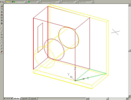
Fig Tsk 36. UCS orientation and the third component in green.
Save your work before moving to the next task.
Please feel welcome to make use of the free resources at the side and bottom of these webpages. Many of them contain very useful 3D CAD material.


