SECTION D23 - TASK 23
Entity directions and the offset command.


Task Twenty Three
Copy each entity a distance of 10mm (0.4 ins) in the minus X and minus Y directions to create the edges of the angle section shown in fig TSK 23. Note the minus values in the sequence below.
| Autocad Command Sequence | Note |
| Command: copy > (Pick the vertical line) | |
| Select objects: 1 found | |
| Select objects: > (Return) | |
| Specify base point or displacement, or [Multiple]: (Pick an end of the line) | |
| Specify second point of displacement or <use first point as displacement >: @0,-0.4,0> (ISO = 0, -10, 0) > | |
| Command: copy > (Pick the horizontal line) | |
| Select objects: 1 found | |
| Select objects: > (Return) | |
| Specify base point or displacement, or [Multiple]: (Pick an end of the line) | |
| Specify second point of displacement or <use first point as displacement >: @ -0.4,0,0> (ISO = -10,0,0) > | |
| Command: |
It is also possible to use the Offset command as in the third command panel of task 8, to achieve the same result.
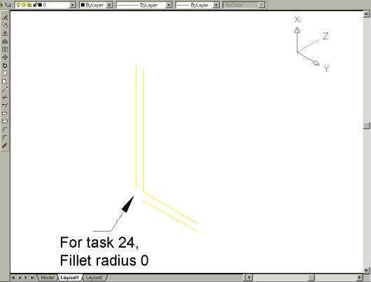
Fig Tsk 23. Creating the angle section with the "Copy" and "Fillet" commands.
SECTION D24 - TASK 24
The Fillet command & zero radius.

Task Twenty Four
Fillet the two new lines with zero radius to join them as shown in fig TSK 23. (AutoCAD may give the same warning as it did in the Note of task 8. If this happens the solution is the same as it was in task 8 to pick specific points.)
| Autocad Command Sequence | Note |
| Command: fillet > | |
| Current settings: Mode = TRIM, Radius = 0.5000 | |
| Select first object or [Polyline/Radius/Trim]: r> | |
| Specify fillet radius < 0.5000 >: 0 > | |
| Select first object or [Polyline/Radius/Trim]: (Pick a line) | |
| Select second object: (Pick the other line) | |
| Command: |
Please feel welcome to make use of the free resources at the side and bottom of these webpages. Many of them contain very useful 3D CAD material.


