SECTION D19 - TASK 19
Creating layers, layer window, chprop, ucs, wcs and xy plane.


Task Nineteen
Layers with specific colours are important. If you are familiar with layers, create a new layer called 01 and set it to color 1 (red) then skip a few paragraphs and go to the heading 'Creating More Layers' and carry on from there. If you are not familiar with layers, the instructions for both older and newer software are given in the next few paragraphs starting with the method for older software. For newer software they are after Fig Tsk 19. (Fig Tsk 19 applies to newer software only.)
Creating the layer and colour for older software is done by typing "layer > n > 01 > c > 1 > 01 > >" Create the layer now and then move to the paragraph with the heading "Creating More Layers" a little further down the page.
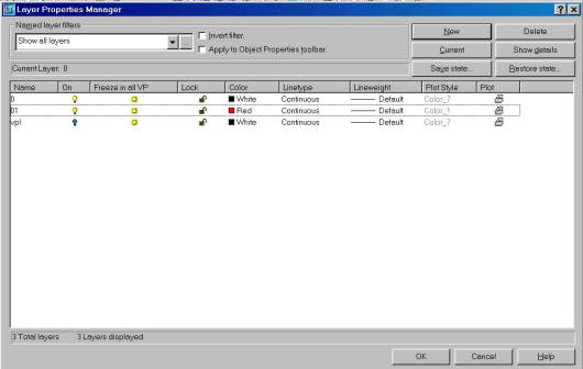
Fig Tsk 19. Creating Layers with newer software.
For newer software, Fig Tsk 19 shows the layer window AFTER the new layer has been created. Start the layer process by typing Layer or click on the layer icon. The layer window appears and the top right hand corner has 6 option choices. Pick the New option. A new layer line appears in the main window, so type 01 in the name column on the left. The colour column near the middle also needs to be set to colour 1 (red.) Click the box icon in the colour column. A new window appears. Select red from the top left of the colour options window and click OK. Finally, click the OK option at the bottom of the window.
Creating More Layers
Repeat this process to create layer names 02 and 03, changing the colours to match the layer names. i.e. Layer 02 is colour 2 (yellow) and layer 03 is colour 3 (green.)
Layers 02 and 03 will be used shortly, but before moving to task 20 it is important to put the box image onto the new layer 01. The circle might need special attention depending on the software version. Pay close attention and follow the instructions carefully.
| Autocad Command Sequence | Note |
| Command: Change > | |
| Select objects: (Try and pick all entities with a crossing window. Read on.) | a./ |
| ?? were not parallel to the UCS. | Continue for now. |
| Select objects:> (Return) | |
| Specify change point or [Properties]: p > | |
| Enter property to change [Color/Elev/LAyer/..etc../LWeight/Thickness]: la > | |
| Enter new layer name <0>: 01 > | |
| Enter property to change [Color/Elev/LAyer/..etc../Thickness]: > (Return) | |
| Command: | |
| a. There is a strong chance that you were not able to pick all the entities. If your software version managed to pick all the entities, finish the instructions in the panel and then read to the end of the task. Entities that could not be picked were created while in a different UCS. Since some releases behave differently to others, there are a couple of methods and one will work. |
|
1)
The easiest is to use the following sequence on the remaining entities:-
Chprop>la>01. If this allows you to change the outstanding
entities to layer 01, then read the rest of the task for reference.
2)
The other method is to set the ucss XY plane in to the same plane as the unchanged
entities prior to changing the layer. Use the UCS command
to manipulate the XY plane in to the same plane as the unchanged items.
(To revise Ucs, see the first panel of Task 6.)
After it is in the same plane, use the Change command again to set the
entities to layer 01. On completion reset the UCS to WCS by using the W modifier.
Please feel welcome to make use of the free resources at the side and bottom of these webpages. Many of them contain very useful 3D CAD material.


For a negligible fee (about the cost of a large cola drink) the full course AND CERTIFICATE can be printed in one go. The small sums it raises cover our costs for running the site. Click here for details.