SECTION D35 - TASK 35
Auxiliary projection, vpoint viewing positions, UCS, & the XY plane.


Task Thirty Five
Saving a UCS and view projections.
This task will set up and save a Ucs in much the same way as "view saving" in task 5. It's convenient to do this now for adding the 3rd component, and it will also be used later when an auxiliary projection is going to be defined. UCS saving is useful because to keep defining it when needed is time consuming and irritating.
Positioning the Ucs uses different options than those previously used in tasks 6 and 8. It means a more convenient Vpoint is needed before setting up the UCS.
Read the rest of this paragraph and then use Vpoint - R to set up a view 120 degrees in the XY plane with a 28 degrees elevation angle from the XY plane. Fig TSK 35 shows the resulting Vpoint. (The command sequence and comment labelled (a) in task 33 might be useful again here to understand your viewing positions. Feel free to experiment with more values for the red prompts from task 33, but finish with 120 and 28.) Save the view with the name "71." (Task 5 to revise view saving.)
Manipulating the Ucs prior to saving it with a name is done as follows:-
| Autocad Command Sequence | Note |
| Command: ucs > | |
| Current ucs name: *NO NAME* Enter an option [New/Move/orthoGraphic/..etc../?/World] <World> n > |
a./ |
| Specify origin of new UCS or [ZAxis/3point/OBject/..etc../X/Y/Z] <0,0,0> 3 > | |
| Specify new origin point <0,0,0> end > | |
| of (Pick end 1 shown in Fig tsk 35) | |
| Specify point on positive portion of X-axis <1.00,-154.24,-137.50> end > | |
| of (Pick end 2 shown in Fig tsk 35) | |
| Specify point on positive-Y portion of the UCS XY plane <1.00,-154.24,-137.50> end > | |
| of (Pick end 3 shown in Fig tsk 35) | |
| Command: | |
| a. Older software may not require the n modifier - move straight to the 3 modifier. |
|
Saving a UCS with a name is like saving a view with a name. The views so far have been called 7, 71 etc. UCS's are the same and it is done as follows:-
| Autocad Command Sequence | Note |
| Command: ucs > | |
| Current ucs name: *NO NAME* Enter an option [New/Move/orthoGraphic/..etc../?/World] <World> s > |
|
| Enter name to save current UCS or [?]: 7 > | |
| Command: | |
|
|
|
The same naming convention can be used for UCSs as well as views. See the next section for an explanation about conventions.
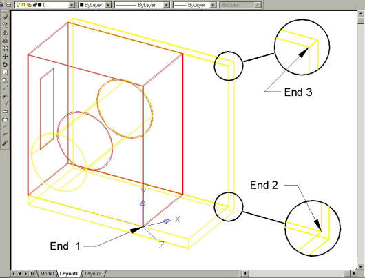
Fig Tsk 35. Picking " End" points.
Naming conventions for views and UCS's
After using the Vpoint command to create a view, (tasks 3 & 10 created some view directions to see the model from certain positions), the view can be saved with a name as was done in task 5. (The view in task 5 was called 7) Exactly the same has just been applied with a newly defined Ucs. It too has just been called 7. The number 7 might seem an odd name at first but does follow a convention.
This convention for naming views and UCSs is derived as a result of a box having 6 faces. Views and UCSs that are in the same plane as a box face can be started with the digits 1 to 6. E.G. If there are several views and UCSs for the face 2 plane, it is reasonable to give them a number starting with 2 such as 21, 22, 23, etc. When views and ucs are not plane to a face, the digits 7, 70, 71 etc can be used with values all the way to 99.
The plan view from the Z direction is usually Face 1 - or just 1, the view from the Y direction is 2, and the view from X direction is 3. Views for faces 4, 5, and 6 are much less common.
Since this is a simple model, double digit names are not necessary so define and save views 1 to 3 for use later on. The commands needed are as follows:-
Vpoint 0,0,1....To create the plan projection.Zoom 0.5X.....To position the view in the middle of the screen.
Set the view name to 1 - start by typing View (Task 5 to revise view names.)
Vpoint 0,1,0
Zoom 0.5X
Set the view name to 2
Vpoint 1,0,0
Zoom 0.5X
Set the view name to 3
If these view names had been created from the outset, the vpoint commands used to create the projection views in Task 10 on pages 34 and 35 could have been replaced by merely restoring views 1 to 3.
Projection views are useful when checking fits and positions. Simply restore one of the saved projection views 1,2 or 3. After you've defined views 1 to 3, restore view 71 as described in the last paragraph of task 5.
Additional pictorial views can be named 72, 73, etc. when the time comes.
Please feel welcome to make use of the free resources at the side and bottom of these webpages. Many of them contain very useful 3D CAD material.


